FZ5435S Ram BOP Shenkai BOP spare
Shenkai BOP spare FZ5435S Ram BOP
Application
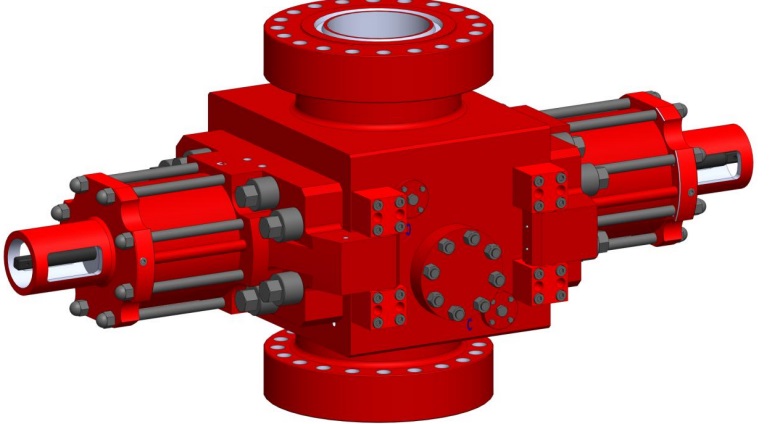
Ram BOP with hydraulic control is a key part of well-control equipment. It’s used for
controlling wellhead pressure during well drilling, workover and testing etc., preventing
well blowout effectively and realizing safe construction. It can be used for the
following:(Figure 1-1):
With proper pipe ram sealing the annular space between casing and drilling
string when there is pipe in the hole;
With blind ram sealing the well head completely
When the well head is closed, use the kill manifold and choke manifold
connected to the spool and the outlet of the body doing mud circulating, choking
and releasing, well killing etc.;
Necessarily, drilling tolls can be hung on pipe ram.
With shear/blind rams shearing the drilling tools to seal the well in some special
Temperature grade
Minimum temperature is namely the minimum environmental temperature that might
be suffered from, and maximum temperature is namely the maximum temperature of the
liquid flowing through the equipment.
Metal parts of the equipment work within the temperature range as shown in Table
2-3.
Working Pressure Code:(Table 2-2)
Bore Code:(Table2-1)
Ram BOP Code:FZ—Single Ram BOP ; 2FZ—Double Ram BOP ;
3FZ—Triple Ram BOP
BOP typeFZ5435S Ram BOP Manual Rev.B0
3
Synthetic rubber materials in the equipment, contacting with the liquid in the well,
work at the temperature grade as shown in Table 2-4.
Working Principles and Structure Characteristics
3.1 Working principle
3.1.1 Hydraulic control principle
When pressure oil of hydraulic pressure system is pumped into the closing cavity of left and right cylinder, it pushes the piston with ram shaft and ram
assembly to move to the center along the orbit limited by the guide rid in the ram chamber to realize well sealing. When it pumped into the opening cavity of left and
right cylinder, it pushes the piston with ram
shaft and ram assembly to move to the center to open the wellhead. The conversion valve of hydraulic pressure system controls the ram switch; Ram switch force is direct ratio with the forced
area of piston and the hydraulic pressure on this area.
3.1.2 Principle of Sealing
Ram BOP has 4 sealing parts in order to seal the wellhead effectively. The ram top seal and body seal; sealing between
ram front seal and the pipe; sealing between the body and the side door; sealing between ram and the side door. Produce of ram sealing divided into 2
steps. First when closing the ram, ram shaft affected by hydraulic oil pushes ram front seal rubber to press the front part of sealing distorted and seal off pipe string or
well hole forming front sealing, over compression between the top seal rubber
and the body seal the top part, forming top sealing and accomplishes primary sealing. Second when there is pressure in the well,
it pushes the ram front seal from back part of ram to extrude distortion more deeply, at the same time, the ram up against the body seal face, thus forming reliable
sealing. This is called well pressure assisting sealing
.
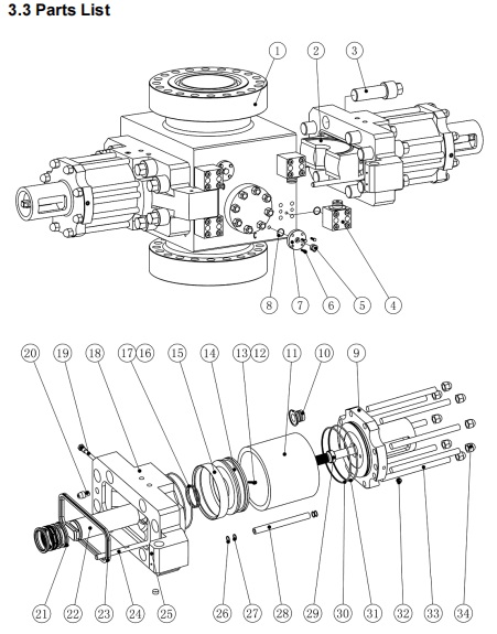
Fig3-1 The Consist parts of Ram BOP
Structural features of main parts
Ram BOP consists of some main parts such as body, side door, cylinder, piston, ram
shaft, locking shaft, cylinder head, and ram assembly etc.
The BOP using the inner flow to avoid
damaging the pipe during installing,
transporting and operating.
Ensure to seal well more safety and
reliable, there is a manual-operated control
system. If the control system of BOP is out of
control, you can use the manual-operated one
to close the ram. If you want to seal well for a
long time, then you can use manual-operated
control system. (See 3.2.8 )
Top, bottom and flange outlet connection
dimensions conform to Specification for
Drilling Through Equipment API Spec 16A.
There is a guide-block on the front end of
ram, it can plug in the groove of the opposite
ram and the slope of guide-block can move
grilling tool toward well bore during closing
rams, ensure reliable sealing between the ram
and drilling tool.
There are high supporting rib and oblique
plane for settling and sloping to the well hole at
the bottom of the ram cavity of the body,
de-sanding automatically when opening and
closing the ram, prevent blocking and reducing
friction of the ram. It is also helpful for well
pressure assisting ram seal.
Main pressure-containing parts such as
body and side door are cast with high-quality
alloy steel, the material conform to NACE
MR-01-75 specification, apply to the working
condition of acid medium and speci`ally heat
treatment. The pressure-containing parts has
do the hydrostatic test in accordance to the
specification of API 16A to ensure safety
during operating under working pressure.FZ54-35S Ram BOP Manual Rev.B0
7
3.2.1 Pipe ram assembly
Ram assembly has an integral design. Top seal and face seal that are separated can
be changed independently depending on different damage situation. So it’s easy to
assemble and disassemble.
Note: The sign of “HO” (Hang-Off) on the ram body indicates that drilling tools could
be hanged on. Drilling tools shall not be hanged on the ram assembly without the sign of
sembly has an integral design. Top seal and face seal that are separated can
be changed independently depending on different damage situation. So it’s easy to
assemble and disassemble.
Note: The sign of “HO” (Hang-Off) on the ram body indicates that drilling tools could
be hanged on. Drilling tools shall not be hanged on the ram assembly without the sign of
"HO".
Fig.3-2 Pipe ram assembly
Table 3-1 Parts of pipe ram
Name
(Qty)
Pipe size
Ram
Assembly
Ram Block(2)
Front Seal(2)
Top Seal(2)
Blind
2S90.01A.00
2S90.01A-01
DFZ5414.47A.02
2S90.01A.03-00
5″
2S90.01B.00
2S90.01B-01
DFZ5414.47B.02
2S90.01A.03-00
5 1/2″
2S90.01C.00
2S90.01C-01
DFZ5414.47E.02
2S90.01A.03-00
7″
2S90.01D.00
2S90.01D-01
DFZ5414.47F.02
2S90.01A.03-00
10 3/4″
2S90.01E.00
2S90.01E-01
DFZ5414.47G.02
2S90.01A.03-00
13 3/8″
2S90.01F.00
2S90.01F-01
DFZ5414.47C.02
2S90.01A.03-00
Lower shear ram body
SBR5435SA-02
1
2
Top Seal
SBR5435SA-05.00
1
3
Front Seal
SBR5435SA-04.00
1
4
Upper shear ram body
SBR5435SA-01
1
5
Top Seal
SBR5435SA-03.00
1
Features of Shear Blind Ram:
Under normal condition, it is used as the full ram, and as the shear ram in case of
emergency; The blade will not be damaged after shearing the drill pipe for several times.
Worn blade can be repaired and reused; the blade and the ram body are integrated; the
front seal of shear ram has a big sealing area with the blade, efficiently reducing the
pressure on the rubber seal and extending the service life.
Operation parameters of shear ram assembly:
When the closing pressure for hydraulic control is ≤21MPa, the drillpipe at level of
5″ G-105 PSL-1 and the thickness at 9.19 mm can be sheared; the maximum working
pressure of sealing could be 35MPa.
Variable diameter ram assembly
The variable
diameter ram is
comprised of variable
diameter ram body, top
Seal and the front
variable
Seal. The
variable diameter ram in
the BOP has the same
installation method with
common ram. None of
any part of BOP has to
be changed.
The
maximum working
pressure of sealing could
be 35MPa.
Table
Variable diameter ram assembly
The variable
diameter ram is
comprised of variable
diameter ram body, top
Seal and the front
variable
Seal. The
variable diameter ram in
the BOP has the same
installation method with
common ram. None of
any part of BOP has to
be changed.
The
maximum working
pressure of sealing could
be 35MPa.
Table 3-3Parts list of variable diameter ram assembly
No.
Name
VBR5435SA.00
_
4 1/2" – 5 1/2"
P/N
Qty
1
Front Seal
VBR5435SA.02.00
2
2
Top Seal
VBR5435SA.03.00
2
3
Ram body
VBR5435SA.01.00
2
4
Screw
GB/T70.1 M12×135
2