
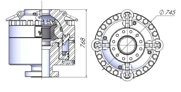
7 3K 7 5000PSI Annular BOP shaffer type
7 1/16"-3000PSI/7 1/16"-5000PSI
7 1/16"-3000PSI/7 1/16"-5000PSI Annular Blowout Preventer must be equipped with hydraulic
control system to use. It is usually used with ram BOP, but it can be used solely. It can complete
following operations:
It can seal on almost any shape or size: Kelly, drill pipe, tool joints, drill collars, casing or wire line.
When there is no drilling tool in preventer, it can completely shut off the hole.
With an accumulator, forced tripping with 18°/35° welded tool joints is allowed It could be used as a
diverter system equipping with a diverter spool.
Technical parameters
The structure of 7 1/16"-3000PSI/7 1/16"-5000PSI Annular BOP is Model ball. It can reliably seal on
almost any shape or size pipe and can also seal a hole without anything in it. Forced tripping is allowed
when the BOP is shut. Reliable sealing, high working pressure, easy to operate and maintain & swift to
close and open is its advantages.
ANNULAR BLOW OUT PREVENTER
Working Principle
When there is the need of sealing well upon kick, the high pressure oil (10.5MPa) from the
hydraulic control system enters the closing chamber at the bottom of piston through the lower hydraulic
port to push the piston upward to force the element to move towards center, the segments close together
to extrude the in-between rubber to the center of wellhead to seal drilling tools or full wellbore. When
opening, the hydraulic control pressure oil enters the opening chamber at the top of piston through upper
oil inlet to push the piston downward, the element returns to original position under the action of its own
elasticity and opens the wellhead.
Features of structure
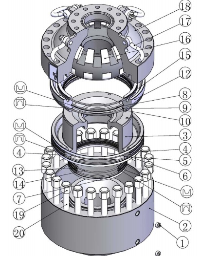
Please see figure 3 &4 for details.
4.1. Simplicity and reliability of structure
7 1/16”-3000PSI/7 1/16-5000PSI annular BOP is constituted by 5 main parts of body, head, piston,
Support Ring, and packing unit. The number of parts is small to enable the BOP to be more reliable and
easy for service, and the cover and the shell are jointed by bolts, so it is convenient to be dismantled on
site. (Refer to Figure 4)
4.2. Compact structure
Only two(2) joints for hydraulic connection “close” & “open”, easy to operate;
Light weight.
4.3. Lip seal structure
All of the power seals are lip structure that could reduce the wear greatly. This structure is more
reliable to avoid leakage.
4.4. Trim H2S
The part inside the BOP which will touch the drilling fluid can trim H2S, meeting the NACE
MR-01-75 requirements
4.5. Packing unit
(1) The element is in balled shape, produced with segments and vulcanized rubber, and the
molded-in segments are made of alloy steel. It’s of long service life. (Ref. figure 5)
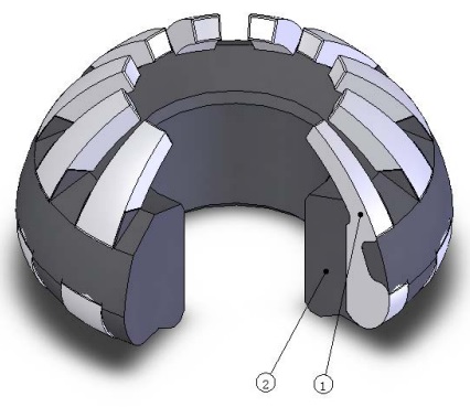
(2)stabilization: During sealing condition, the well pressure will force the central rubber of rubber
to turn upward, but the upper bars of segments will stop such turn to keep the rubber in the safe and
compressed status, so the packing unit could bear larger pressure without tearing.
(3)Assistance of well pressure for sealing: During closing period, the well pressure acting on the
annular area in upper part of inner cavity of piston will push the piston upward, which promotes the tight
sealing of rubber, enhances the reliability of sealing, and therefore reduces the pressure on closing and
opening of hydraulic control.
(4) If the packing unit needs to be changed and there are drilling tools inside well, the old packing
unit could be cut an opening between two segments, and taken out. Then the new packing unit will be
cut an opening also, then put in BOP around the drilling tools. (Ref. figure 6)
Operation and maintenance
5.1. Installation
Following systems are required at well site to use the annular BOP.
⑴ Hydraulic control system;
⑵ Control hoses to the closing hydraulic port;
⑶ Control hoses to the opening hydraulic port;
⑷ For stripping, an accumulator bottle is required. The bottle should be pre-charged with nitrogen to
a special pressure
⑸ To meet any situation, a hydraulic regulator should be equipped to adjust operating pressure.
5.2. Stripping operation
Stripping operations are undoubtedly the most severe application for any preventer, because the
packing unit will wear greatly as the drill string move through the preventer under pressure. To prolong
sealing element life, it is important to use proper operating procedures when stripping. The
recommended procedures are as follows:
⑴ Close the preventer with 1500psi closing pressure.
⑵ Just prior to stripping operations, reduce closing pressure to a value sufficient to allow to a slight leak.
The slight leak can provide lubrication and prevent excessive temperature build up in the element. As
the element wears too much, the operating pressure will need to be incrementally increased to
prevent excessive leakage. Note: only string with 18°tool joints could be used, and the tripping speed
could not exceed 0.2m/s.
If conditions will not allow leakage during stripping operations, the closing pressure should be
adjusted to a value just sufficient to maintain a seal;
⑷ As required closing pressures approach 1,500psi, excessive leakage still exists, it is said that the
rubber has been worn seriously. It must be solved first, and then stripping operations could be
continued.
5.3. Proper application
⑴ After installation at well site, the BOP should be pressure tested according to related standards.
⑵ After reaching the target stratum, the BOP should be checked by closing and opening it every two
stripping. If there is any problem, it must be solved immediately.
⑶ When a blowout happens with drill string in the well, the annular BOP can be used to control the well
pressure first, but it can’t be used for a long time because the service life of the rubber will be shorten
greatly, and it does not has locking system.
Normally, don’t use the BOP to shut off a well without pipe in.
Caution: shutting off an empty well completely, the max well pressure should be half of the rated
working pressure.
⑷ When the BOP sealing a pipe string, the drill string could move up and down, but the rotation of drill
string is forbidden.
⑸ Do not release well pressure by opening annular BOP to avoid rubber damage
⑹ Every opening procedure, its full opening position must be checked to avoid rubber damage.
⑺ Opening and closing operation must use hydraulic oil, and the oil must be kept clean;
⑻ the recommended max operating pressure is 1500PSI (10.5MPa).
Parts and disassembly
6.1. Disassembling procedure
6.1.1. Change of packing unit
(1)Remove the head cap nuts(Item 19)
(2)Lift head out evenly;
(4)Screw the eyebolts into the packing unit and lift it out. If there are drilling tools in it, the new and
old packing unit should be cut a opening between two segments with rubber cutter and
crowbar first, and rubber cutter should be lubricated with suds. Such blunt cutting tools as saw
blade etc are forbidden. The cutting surface should be smooth. Then lift the old packing unit
out and put the new one in BOP.
6.1.2. Disassembling procedures of piston and Support Ring
(1)after removing packing unit, screw eye bolt in dust proof ring and lift it out evenly;
(2)after removing packing unit, screw eye bolt in piston and lift it out evenly;
6.2. Assembling procedure
1. Check whether the seal rings are ok, they should be changed if they are damaged or aged;
2. Lubricate the inner surface of body, piston by mechanical oil.
3. Install piston in
4. Install Support Ring in
5. Install packing unit in. The packing unit’s surface should be coated with aluminum base grease or
drill pipe sealing grease;
6. Install head. The head’s inner surface should be coated with aluminum base grease or drill pipe
sealing grease;
7. Install head by screw(item 19、20);
8. tighten screw(item 19, recommended torque is 400-540N.m), during tightening, relieve the
screw(item 19)first, and at last tighten them
9. Screw on a plug on the hydraulic port avoiding garbage entering (inlet of closing and opening)
7. Proper storage of rubber parts
The storage condition will influence rubber parts’ service life greatly. The perfect storage condition is
a cool, dark and dry warehouse and the rubber parts should be packed in bags. All rubber parts should
be stored as following if you do not have perfect conditions:
1. Always use the oldest rubber part first. New parts should be placed at the back of the bin, so that
old parts will be used first.
2. Definitely do not store rubber parts out of doors. Rubbers should be stored in dark, cool (0-25ºC)
and dry room (humidity is less than 80%). Keep them away from heaters and direct sunlight
3. Do not spill corrosive material on rubber parts; Keep storage area as cool as possible. Never
store rubber parts near heaters, steam pipes, radiators or other hot equipment.
4. Store these items away from high-voltage equipments. High-voltage equipment frequently
produces ozone that attacks rubber.
5. Rubber parts should be placed in a relaxed position. Do not bend, extrude or hang them. For
example, bending a rubber part and forcing it into a small box will accelerate aging the stressed
area.
6. Check rubber parts often, the parts with brittleness, crackle, bending should be abandoned.
7. Generally the storage period is 2 years.
8. Trouble shooting
8.1. The rubber can not seal pipe completely
⑴ If a new packing unit could not seal pipe completely, it could be opened and closed for several
times to improve its flexibility, and then it will be ok. But it should be changed if it still can’t seal
pipe completely even all steel segments close together completely.
⑵ If the rubber is over worn or damaged, it should be changed in time
⑶ If a BOP has been opened for a long time, some garbage will fill in the grooves of packing unit
and block its movement. The packing unit should be cleaned, and then opened & closed for
several times to solve this problem.
8.2. The BOP can not opened after closing
It’s due to the packing unit’s permanent deformation because of long time closing or the
concretionary cement under packing unit after cementing. Cleaning or changing packing unit will solve it.
8.3. The BOP can not be opened and closed flexibly.
⑴ Prior to connecting, All pipes should be blew with pressure air. All connectors should be cleaned.
⑵ The hydraulic oil leakage, long-time inaction and blocking up will weaken the flexibility of operation. So
BOP must be operated according to the operation procedure.
Ordering
When ordering an annular blowout preventer, the following should be detailed:
1. Bore size and working pressure
2. Connection type: Top and Bottom connection size, working pressure and ring groove size;
3. Working temperature range: Include metal & rubber parts temperature grade;
4. Ring grooves needs to be lined with stainless steel or not;
5. Requirements of resistance to Hydrogen sulfide;
6. Additional spare parts;
7. Other special requirements: such as metric or British system (for thread and screw)


