Jiangsu Rongling Machinery Manufacturing
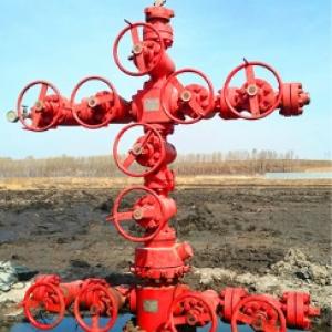
Jiangsu Rongling Machinery Manufacturing Co., Ltd. is located in the private industrial park of Jianhu County, Jiangsu Province, China's petroleum equipment manufacturing base. It is a one-stop service enterprise engaged in the production and sales of ground blowout preventers and control devices, oil (gas) wellhead devices and casing heads, throttling and well control manifolds, throttling manifold control boxes, pneumatic pressure testing pumps, offshore platform pipelines, valves and other related products.
The company has strong management capabilities, complete product specifications and varieties, strict testing methods, and reliable product quality.
Jiangsu Rongling Machinery Manufacturing Co., Ltd. strictly adheres to the * * * standard for all products and has obtained ISO 9001 international quality system certification. The company adheres to the principle of "quality comes from focus, service creates brilliance" and strives to build the corporate philosophy of "production and service". It promotes corporate culture internally and disseminates corporate spirit externally, continuously improves product quality, and enhances corporate image.Main business: fK125-3 ground blowout preventer control device, blowout preventer ground control device, oilfield ground blowout preventer control device, blowout preventer ground control device supplier, wellhead equipment, drilling control device, petroleum drilling control device.
JIANGSU RONGLING MACHINERY MANUFACTURING CO., LTD
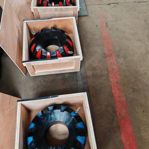
he ground blowout preventer control device is an important equipment for controlling the wellhead blowout preventer group, hydraulic throttle valve, and well control valve. It is an indispensable device in drilling and operation. The ground blowout preventer control device meets the requirements of the petroleum industry standards and has the right to use the API SPEC 16D (Drilling Control Equipment Control System and Diversion Equipment Control System) emblem. The product has multiple models and comprehensive functions, meeting the requirements for regular use. In addition to the specifications and models listed in this introduction, special models of products can be designed according to different configurations requested by customers.
Performance Characteristics
The remote console is equipped with two independent power sources. According to different configurations, provide electric oil pumps with different displacements, pneumatic oil pumps, or manual oil pumps. The design of the accumulator group meets the control requirements of closing all blowout preventer groups and opening hydraulic valves. The accumulator system is designed such that when one or a group of accumulators fail, the capacity loss does not exceed 25% of the total capacity, and can provide accumulators with ASME inspection marks. The control device with manual pressure regulating valve has remote pneumatic pressure regulation function. When the gas source suddenly fails, the control pressure can automatically return to the initial set value. There is a backup pressure source interface on the control manifold of the remote console, which can introduce a pressure source when needed. A nitrogen backup system can be provided as needed to provide emergency auxiliary energy for the control manifold. When the accumulator and/or pump device cannot provide sufficient power fluid for the control manifold, a nitrogen backup system can be used to provide high-pressure gas to the manifold in order to close the blowout preventer. The nitrogen backup system can also provide emergency gas source for the drilling rig and auxiliary control console in case of emergency.
The blowout preventer is suitable for closing the wellhead during oil testing, well repair, completion and other operations to prevent blowout accidents. It combines the functions of full sealing and semi sealing, and has the characteristics of simple structure, easy operation, high pressure resistance, etc. It is a commonly used safety sealing wellhead device in oil fields to prevent blowout.
The feature of the remote console is that it is equipped with two independent power sources. The series is equipped with electric and pneumatic oil pumps, which can ensure the normal operation of the system even in the event of power failure. The accumulator group has sufficient high-pressure liquid reserve to achieve the opening and closing of the blowout preventer. The accumulator group system is divided into four groups. When one or a group of accumulators fails, the capacity loss shall not exceed 25% of the total capacity. Each group of pipelines is equipped with a pressure source isolation valve and a pressure relief valve. The pressure relief valve is equipped with a pressure relief pipeline, which can also discharge the pressure outside the bottle.
Both electric and pneumatic oil pumps are equipped with automatic start and stop control devices. Even if the automatic control device fails during normal operation, the overflow valve can quickly overflow to ensure system safety. The opening and closing actions of each blowout preventer are controlled by the corrESPonding three position four-way rotary valve. The FKQ series hydraulic control device can be directly switched manually or remotely controlled by pneumatic means.
Both electric and pneumatic oil pumps are equipped with automatic start and stop control devices. Even if the automatic control device fails during normal operation, the overflow valve can quickly overflow to ensure system safety. The opening and closing actions of each blowout preventer are controlled by the corresponding three position four-way rotary valve. The FKQ series hydraulic control device can be directly switched manually or remotely controlled by pneumatic means.
Adjustment of pressure relay: Set the control knob of the ground blowout preventer control device's electrical control box to the 'automatic' position and start the electric pump. If the electric pump does not work, it may be due to low switching point pressure or large switching difference. Raise the pressure at the switching point to start the pump. After the electric pump is running, observe the increase in system pressure and record the pressure at which the pump automatically stops running. Remove the plug on the lower right side and adjust it by adjusting the mechanism to increase or decrease the switching point pressure value. Restart the Motor and observe the system pressure. Repeat this process until the switching point pressure approaches 21MPa (3000psi), which means the electric pump can automatically stop at 21MPa (3000psi). After the electric pump stops automatically, slowly loosen the unloading valve of the manifold, and the system pressure starts to decrease from 21MPa. Observe the pressure at which the electric pump starts automatically. When the starting pressure exceeds the required 18.5MPa, remove the plug on the upper right side and adjust it through the adjustment mechanism to increase the switching difference and reduce the starting pressure. On the contrary, to increase the starting pressure, the switching difference should be reduced. Attention: During the adjustment process, the switching difference and the set value of the switching point may affect each other, so repeated adjustments may be necessary to ultimately meet the control requirements.
The FKQ series control device requires connecting the air source pipeline and air duct cable. When connecting air ducts and cables, attention should be paid to the direction of the connecting flanges, and sealing gaskets should be placed between the flange surfaces, and bolts should be tightened evenly. The remote console air source is connected using a hose with an inner diameter of 32mm, while the driller console air source is connected using a hose with an inner diameter of 16mm. The connection between the hose and the joint must be clamped tightly with a hose clamp to prevent loosening. The hose should be free of defects such as aging and cracking to prevent bursting during use. When connecting the gas pipeline, it should be ensured that there are no dead bends in the pipeline, the pipeline joints are reliably connected, and faults such as pipeline rupture and slippage at the connection should be avoided. When connecting the flanges at both ends of the air duct cable, if the sealing gasket is not properly padded or the connecting bolts are not evenly tightened, it will cause air leakage between the pipelines, leading to misoperation.
As one of the important well control devices in modern drilling operations, the blowout preventer can seal the annular space between the casing and the drilling tool when there are drilling tools or other pipes in the well; When there are no drilling tools in the well, the wellhead can be fully closed. In the closed state, drilling fluid circulation, throttling and blowout, and well killing operations can be carried out through the manifold connected to the outlet on the side of the shell. In special circumstances, the drilling tool can be cut off to achieve the purpose of sealing the well. Its reliability plays a crucial role in preventing and controlling well surges, overflows, and blowouts. In the oil circuit test of the blowout preventer, pressure drop is an important indicator to Measure the reliability of the blowout preventer switch.
throttle manifold
1. Purpose:
Throttle manifold is a necessary equipment for controlling well kick and implementing pressure control technology in oil and gas wells. Under the condition of the blowout preventer being closed, the opening and closing of the throttle valve is used to control a certain casing pressure to maintain the bottomhole pressure slightly higher than the formation pressure, avoiding further inflow of formation fluids into the well. In addition, when implementing well shut in, a pressure relief manifold can be used to achieve soft shut in. When the pressure inside the well reaches a certain limit, it is used to release water to protect the wellhead.
2. Composition and Structure
The throttling manifold consists of throttling valves, gate valves, pipelines, pipe fittings, pressure gauges, etc.
3. Working principle
When the pressure inside the well increases, the fluid inside the well can be released to control the casing pressure by opening and closing the throttle valve (which can be manually adjusted, hydraulic, or fixed) on the throttle manifold. When the casing pressure is high, it can be directly sprayed through a gate valve.
4. Specification of throttling manifold
Our company's throttling manifold has five pressure levels, namely 14MPa, 21MPa, 35MPa, 70MPa, and 105MPa. It can also be designed according to customer requirements.
5. Usage requirements
(1) The working pressure of all components of the throttling manifold should match the working pressure of the combination of the blowout preventer used;
(2) The throttling manifold should be installed in a location easily accessible to operators, and pressure testing must be conducted during installation. The sealing test pressure should be equal to the rated working pressure;
(3) Pipelines should be as straight as possible, and 120 degree cast steel bends should be used at pipeline bends. The pipeline should have a sufficiently large aperture;
(4) A work pressure gauge must be installed;
(5) During winter construction, the throttling manifold should have the ability to operate under low temperature conditions.
The throttling manifold meets the requirements of API Spec 16C standard:
Working pressure: 2000psi~15000psi
Nominal diameter: 2-1/16 '~4-1/16'
API Spec 16C Certificate (Certificate Number: 0019)