
Shaffer Ram BOP pressure Test and Maintenance
Shaffer Ram BOP pressure Test and Maintenance
From Cangzhou Fengliang Petroleum Machinery Co.,Ltd
Application
The ram blowout preventer is one of the key elements of the well control system. It is mainly used to control the well head pressure during such operations as drilling, servicing and oil testing to prevent any blow out hazard effectively and ensure safe operations. Specifically, it can be used for the following operations:
² When there is a pipe string a well, the circular space between the casing and the drill pipe could be
sealed with matched pipe rams.
² When there isn’t a pipe string in a well, the wellhead could be shut off completely with blind rams.
² After the well has been sealed, such special operations as mud circulation, choking, killing and well
washing can be performed through choke and kill manifold connected to spool and side outlet of BOP.
² When used together with the pipe manifold for choking and killing, it can control the well pressure
effectively and achieve near-balance well killing operations.
2. Technical Parameters
Nominal Working Pressure: There are six kinds of working pressures as listed in the following table.
Table 2 Nominal Working Pressure Rating
|
14MPa(2,000psi), |
21MPa(3,000psi) |
35MPa (5,000psi) |
|
70MPa (10,000psi) |
105MPa(15,000psi) |
140 MPa(20,000psi) |
2. Temperature Grades of Metal Materials:
Table 3 Temperature Grades of Metal Materials
|
Temperature Grade Code |
API Code |
Working Temperature Range |
|
T75 |
75 |
-59~121℃(-75~250 ºF) |
|
T20 |
20 |
-29~121℃(-20~250 ºF) |
|
T0 |
00 |
-18~121℃(0~250 ºF) |
3. Temperature Grades of Non-metal Sealing Elements in contact with Well Liquids.
Combinations of two letters are used to indicate the upper limits and the lower limits as described below.
Lower Limit (First Letter) Upper Limit (Second Letter)
A 15ºF(-26℃) A 180ºF(82℃)
B 0ºF(-17.8℃) B 200ºF(93℃)
C 10ºF(-12.2℃) C 220ºF(104℃)
D 20ºF(-6.7℃) D 250ºF(121℃)
E 30ºF(-1℃) E 300ºF(149℃)
X 40ºF(4℃) X 180ºF(82℃)
For example, AB represents a temperature grade ranging from -26℃ to 93℃. The specific temperature grade is marked with a code on a sealing member.
2.2 Technical Parameters of the Ram Blowout Preventer
Please see the following table for the technical parameters:
Table 1 Parameters of Ram Blowout Preventer
|
Item |
Single Ram Blowout Preventer |
Double Ram Blowout Preventer |
||
|
Model |
21 1/4” |
21 1/4” |
||
|
Top Connection |
Studded |
Flanged |
Studded |
Flanged |
|
Bottom Connection |
Flanged |
Flanged |
Flanged |
Flanged |
|
Weight Kg |
4952 |
5202 |
9158 |
9408 |
|
Height (H) mm |
790 |
950 |
1230 |
1400 |
|
Bore Size |
539.7 mm (21 1/4″) |
|||
|
Shell Test Pressure |
21MPa (3,000psi) |
|||
|
Rated Working Pressure |
14MPa (2,000psi) |
|||
|
Hydraulic Control System Strength Pressure |
31.5 MPa(4,500psi) |
|||
|
Hydraulic Control System Working Pressure |
21 MPa(3,000psi) |
|||
|
Recommended Hydraulic Control Operating Pressure |
8.4~10 .5MPa(1,200~1,500psi) |
|||
|
Opening volume for one set of Ram |
22.6L |
|||
|
Closing volume for one set of Ram |
25.5L |
|||
|
Hydraulic Port |
NPT 1 |
|||
|
Side Outlet note |
3 1/16″-15000psi(it’ll change according to different contract) |
|||
|
Temperature Grade note |
T20(-29~121℃) (it’ll change according to different contract) |
|||
|
Closure Ratio |
1: 4.76 |
|||
|
Other Descriptions: The designing and the manufacturing of the blowout preventer are in accordance with the API Spec 16A norms. The resistance to the corrosive stress of hydrogen disulfide of the internal parts of the blowout preventer in contact with the well liquids conforms to the requirements specified in NACE MR-01-75. |
||||
Table 5 Specifications of Available Rams
|
Blind, 2 3/8″,2 7/8″,3 1/2″,4″,4 1/2″,5″,5 1/2″, 6 5/8″, 7″,9 5/8″, 10 3/4″, 13 3/8″, 14″, 16″ |
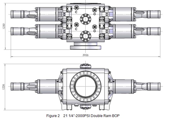
Figure 2 21 1/4”-2000PSI Double Ram BOP
3. Working Principles
3.1 Principles of opening and closing
When high pressure oil of hydraulic control system comes into the left and right closing chambers of cylinders through oil channel inside body from hydraulic port, the impelling Pistons drive ram shafts with ram assemblies to the center of wellhead along ram chamber to close the well. When high pressure oil comes into the left and right opening chambers of cylinders, the impelling Pistons drive the ram shafts with ram assemblies away from the center of the wellhead to open the well. The opening and closing is controlled through the reversal valve of the hydraulic control system.
3.2 Principles of well pressure sealing
A ram blowout preventer can only effectively close a well when all the four seals have taken effect. These four seals include the seal between the ram top seal and the body, the seal between the ram front seal and the pipe, the seal between the body and the bonnet, and the seal between the ram shaft and the bonnet.
The ram sealing process is divided into two steps. In the first step the hydraulic oil forces the ram shaft to impel ram packer to deform and seal the front part, and top seal seals top with compressed rubber, so it establishes a primary sealing. In the second step, with the help of the pressure inside the well the rams are impelled from behind to make ram packer deform more and the rams are also impelled from the bottom to let the body adhere tightly to top, thus achieve the reliable sealing. It is called the well pressure assisted sealing effect.
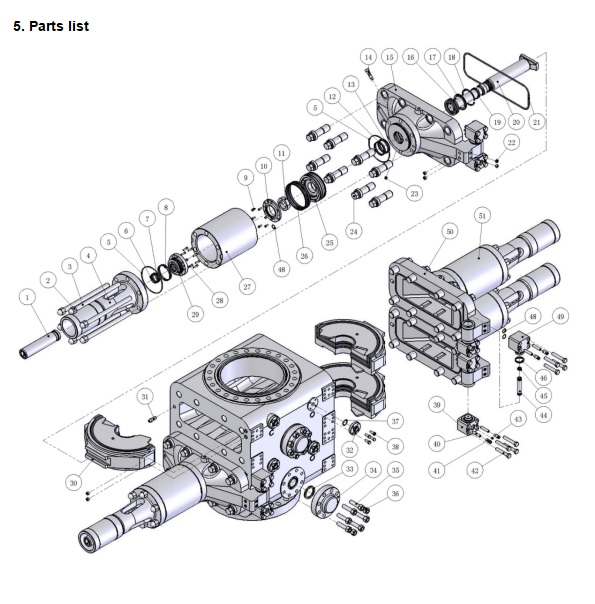
4. Structures and features
4.1 Structural Features
Ø Such major pressure bearing components as body, bonnets and ram blocks are cast formed with alloy steels of high strength and high malleability, and properly heat treated. And the water pressure test for strength is performed before ex factory according to API specifications.
Ø At the bottom of ram chamber, there are high brace rods and sand-depositing slots towards the well bore. So the sands and silts will be removed automatically when the rams’ opening and closing. It reduces the kinetic frictional resistance of the ram, and is also helpful to the well pressure assisted sealing of the ram. The surface of ram chamber is smooth and easy to clean.
Ø A kind of floating ram sealing is adopted to reduce the resistance in opening or closing the ram, minimize the wearing of the rubber elements and lengthen the service life of the ram. It also prevents the body and ram from rusting together and thus is easy to disassembly.
Ø The ram shaft retainers are made of stainless steel, and retainers’ grooves are lined with stainless steel. The BOP is of high anticorrosive ability.
Ø The top seal surface of ram chamber is chemically coated with nickle for anticorrosion.
Ø Rams are HF type which is easy to change and maintenance.
Ø The internal parts and surfaces of BOOP contacting with well fluids are resistant to the corrosive stress of hydrogen disulfide and conform to the requirements specified in NACE MR-0175.
Ø The dimensions of the external connections are in conformity with the API 6A.
Pipe Ram
There are two kinds of ram assemblies (“H” and “HF” type). “H” type is old design, the new “HF” type is recommended.
6. Installation, application and cautions
Before installing the blowout preventer please make sure that you have read the above chapters of this manual, where the structures, functions and operation methods of each component of this blowout preventer are described in detail. Then you can install and use this blowout preventer following the procedures described below.
6.1 Installation on the Wellhead
6.1.1 The following checks shall be performed before installing this ram blowout preventer:
(1) Check the integrity of the circle slot for the seal gaskets of the flanges of the wellhead and the blowout preventer and check that there are no bulging points on the surfaces of the flanges.
(2) Check whether the specifications of rams in BOP are compatible with the dimensions of the drilling tools in the well.
(3) Check that it passed the pressure test.
6.1.2 Installation of the Ram Blowout Preventer
(1) Tighten the coupling bolts of each flange homogenously cornerwise one by one. Please see Table 11 or Table 12 for the tightening torque of the bolts of each flange.
(2) Connect the hydraulic control line and pay attention to the marks for the open and closure of the blowout preventer.
(3) Connect the manual control rods.
Table 11 Recommended Tightening Torques of the Bolts and Screws (Metric)
|
Size of Bolts and Screws |
Tightening Torque (N·m) |
Size of Bolts and Screws |
Tightening Torque (N·m) |
Size of Bolts and Screws |
Tightening Torque (N·m) |
|
M12 |
80 |
M33×3 |
1292 |
M52×3 |
5505 |
|
M16 |
153 |
M36×3 |
1737 |
M58×3 |
7892 |
|
M20 |
266 |
M39×3 |
2272 |
M64×3 |
10885 |
|
M22 |
424 |
M42×3 |
2910 |
M70×3 |
14549 |
|
M27 |
643 |
M45×3 |
3654 |
M76×3 |
18957 |
|
M30×3 |
930 |
M48×3 |
4516 |
M80×3 |
21565 |
Table 12 Recommended Tightening Torques of the Bolts and Screws (British)


