
cameron Ram BOP test pressure
Cameron Ram BOP test pressure and Maintenance
. Application
The ram blowout preventer is one of the key elements of the well control system. It is mainly used to control the well head pressure during such operations as drilling, servicing and oil testing to prevent any blow out hazard effectively and ensure safe operations. Specifically, it can be used for the following operations:
² When there is a pipe string a well, the circular space between the casing and the drill pipe could
be sealed with matched pipe rams.
² When there isn’t a pipe string in a well, the wellhead could be shut off completely with blind rams.
² After the well has been sealed, such special operations as mud circulation, choking, killing and
well washing can be performed through choke and kill manifold connected to spool and side outlet of BOP.
² When used together with the pipe manifold for choking and killing, it can control the well pressure
effectively and achieve near-balance well killing operations.
2. Technical Parameters
Nominal Working Pressure: There are six kinds of working pressures as listed in the following table.
Table 2 Nominal Working Pressure Rating
|
14MPa(2,000psi), |
21MPa(3,000psi) |
35MPa (5,000psi) |
|
70MPa (10,000psi) |
105MPa(15,000psi) |
140 MPa(20,000psi) |
2. Temperature Grades of Metal Materials:
Table 3 Temperature Grades of Metal Materials
|
Temperature Grade Code |
API Code |
Working Temperature Range |
|
T75 |
75 |
-59~121℃(-75~250 ºF) |
|
T20 |
20 |
-29~121℃(-20~250 ºF) |
|
T0 |
00 |
-18~121℃(0~250 ºF) |
3. Temperature Grades of Non-metal Sealing Elements in contact with Well Liquids.
Combinations of two letters are used to indicate the upper limits and the lower limits as described below.
Lower Limit (First Letter) Upper Limit (Second Letter)
A 15ºF(-26℃) A 180ºF(82℃)
B 0ºF(-17.8℃) B 200ºF(93℃)
C 10ºF(-12.2℃) C 220ºF(104℃)
D 20ºF(-6.7℃) D 250ºF(121℃)
E 30ºF(-1℃) E 300ºF(149℃)
X 40ºF(4℃) X 180ºF(82℃)
For example, AB represents a temperature grade ranging from -26℃ to 93℃. The specific temperature grade is marked with a code on a sealing member.
2.2 Technical Parameters of the Ram Blowout Preventer
Please see the following table for the technical parameters:
Table 1 Parameters of Ram Blowout Preventer
|
Item |
Single Ram Blowout Preventer |
Double Ram Blowout Preventer |
||
|
Model |
13 5/8” |
13 5/8” |
||
|
Top Connection |
Studded |
Flanged |
Studded |
Flanged |
|
Bottom Connection |
Flanged |
Flanged |
Flanged |
Flanged |
|
Weight Kg |
7888 |
8807 |
14572 |
15491 |
|
Height (H) mm |
1085 |
1430 |
1745 |
2090 |
|
Bore Size |
346.1 mm (13 5/8″) |
|||
|
Shell Test Pressure |
157.5MPa (22,500psi) |
|||
|
Rated Working Pressure |
105 MPa (15,000psi) |
|||
|
Hydraulic Control System Strength Pressure |
31.5 MPa(4,500psi) |
|||
|
Hydraulic Control System Working Pressure |
21 MPa(3,000psi) |
|||
|
Recommended Hydraulic Control Operating Pressure |
8.4~10 .5MPa(1,200~1,500psi) |
|||
|
Opening volume for one set of Ram |
37L |
|||
|
Closing volume for one set of Ram |
40L |
|||
|
Hydraulic Port |
NPT 1” |
|||
|
Side Outlet note |
3 1/16″-15000psi (it’ll change according to different contract) |
|||
|
Temperature Grade note |
T20(-29~121℃) (it’ll change according to different contract) |
|||
|
Closure Ratio |
1: 9.5 |
|||
|
Other Descriptions: The designing and the manufacturing of the blowout preventer are in accordance with the API Spec 16A norms. The resistance to the corrosive stress of hydrogen disulfide of the internal parts of the blowout preventer in contact with the well liquids conforms to the requirements specified in NACE MR-01-75. |
||||
Table 2 Specifications of Available Rams
|
Blind, 2 3/8″,2 7/8″,3 1/2″,4″,4 1/2″,5″,5 1/2″, 6 5/8″, 7″,9 5/8″, Shear |
3.2 Principles of well pressure sealing
A ram blowout preventer can only effectively close a well when all the four seals have taken effect. These four seals include the seal between the ram top seal and the body, the seal between the ram front seal and the pipe, the seal between the body and the bonnet, and the seal between the ram shaft and the bonnet.
The ram sealing process is divided into two steps. In the first step the hydraulic oil forces the ram shaft to impel ram packer to deform and seal the front part, and top seal seals top with compressed rubber, so it establishes a primary sealing. In the second step, with the help of the pressure inside the well the rams are impelled from behind to make ram packer deform more and the rams are also impelled from the bottom to let the body adhere tightly to top, thus achieve the reliable sealing. It is called the well pressure assisted sealing effect.
4. Structures and feature、、
4.1 Structural Features
Ø The opening and closing for both rams and bonnets are all actuated hydraulically by one and same hydraulic path. The bonnets’ opening and rams’ closing are actuated by one and same hydraulic path and action; then the bonnets’ closing and rams’ opening are actuated by one and same hydraulic path and action
Ø Ram assembly: ram bodies are in long-round shape. Ram rubber is divided into two parts: front packer and top seal. This structure is easy and convenient for ram rubber to change. The front packer and top seal could be changed rESPectively according to damage condition in fact.
Ø Between body and bonnets, a floating well-pressure-assistant-sealing structure is used on bonnet. So need less pre-tighten force is needed, and it’s reliable.
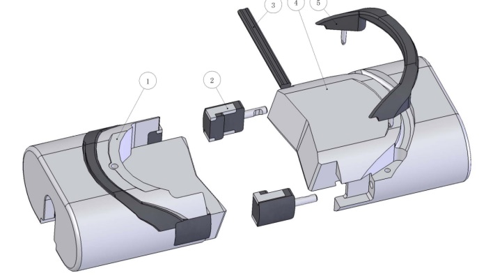
5. Parts list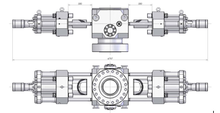


6.2.3 Testing of the Hydraulic Control System
The rated working pressure of the hydraulic control system of the blowout preventer is 21MPa (3,000psi). The opening and closing should be tested separately. The testing media is the hydraulic oil.
A. without rams or bonnet is rotate to the open position. Pay attention not to let the ram shaft touch the body when it is protruded. The blowout preventer should be fixed to ground to prevent it from falling because of the shift in the center of gravity after the two bonnets have been opened at the same time.
B. Perform the testing of the closure chamber under a pressure of 21MPa (3,000psi) and hold this pressure for 10 minutes. It is qualified if there is no any leakage.
C. Reduce the hydraulic control pressure to zero.
D. Perform the testing of the opening chamber under a pressure of 21MPa (3,000psi) and hold this pressure for 10 minutes. It is qualified if there is no any leakage.
E. Reduce the hydraulic control pressure to zero.
6.3 Precautions
1. It is forbidden to release the pressure by opening the ram to avoid damaging the rubber elements. Check whether the manual locking device has been unlocked every time before opening the ram. After opening, the rams should be checked whether they are fully opened (drawn back completely inside the body) to avoid damaging the ram by the drilling tools.
2. It is forbidden to rotate the drilling tools when the ram is closed.
3. Pay attention to keep the hydraulic pressure oil clean.
4. After using or testing the blowout preventer, the water inside it shall be completely drained. The ram shall be kept at the fully opened position, and rust-proofing Measures shall be taken.
7. Maintenance and Servicing
The blowout preventer shall be thoroughly cleaned and inspected after serving each well. Damaged parts shall be replaced in time, ram chamber and ram assembly shall be coated with rust proof oil (aluminum base grease is recommended). All rust proof oil should not melt under 50℃; all threads should be coated with thread oil.
7.1 Replacement of the rams and ram rubbers
The ram sealing rubber elements are the key components for the successfully well closing. It is impossible to use once it is damaged. So they should be kept intact without any defects. Once a defect is found it should be replaced in time. The procedures for the replacement of the ram and the ram rubbers are as follows:
▲!Pay attention to make sure that the manual locking device is in the unlocking position.
(1) Open the rams fully hydraulically;
(2) Loosen bonnet bolts. Note, bonnet bolts must not be opened when there is well pressure in BOP;
(3) Close oil valve tightly;
(4) Open bonnet hydraulically with operation pressure ≤10.5MPa (closing ram) to full-opening position;
(5) Open rams hydraulic to full-opening position if the rams are not at full-opening position. Stop hydraulic operation when rams are at full-opening position in order to prevent bonnet from closing; Place two (same dimensions) pieces of wood between bonnet and body if necessary;
(6) Take out ram assemblies out by lifting upward from the tail of the ram shaft. Pay attention to protect the sealing surface, the ram, ram shaft and bonnet from being knocked or scratched;
(7) When replacing the rubber element of the ram, first pry the top seal, then dismount the packers, and replace it with a new one. Repeat the above procedures reversely to assemble it.
7.2 Reparation and change of cylinder assembly
If there are any damages or leakages of oil at the ram shaft sealing, the piston sealing or the locking shaft sealing, they should be disassembled and repaired.
7.2.1 The specific procedures are described below.
(1) Open bonnet hydraulically with operation pressure ≤10.5MPa (close ram), and lift out ram assemblies;
(2) Discharge pressure in cylinder: place a clean basin under cylinder to prevent oil flow on ground;
(3) Disassemble studs and nuts of locking shaft housing, then disassemble locking shaft housing and locking shaft, and hammer locking shaft out of housing;
(4) Disassemble cylinders, ram change cylinders;
(5) Draw out ram shaft;
(6) Lift bonnet with crane, then disassemble ram change Pistons;
(7) Disassemble retainer, take out ram shaft seals ring and locking shaft seals ring.
7.2.2 Examination positions after disassembly
(1) Inner wall of hydraulic cylinder
If there are any deep longitudinal scratches in the inner surfaces of the hydraulic cylinder and leakages cannot stop even after replacing the seal ring of the piston, it shall be replaced with a new hydraulic cylinder. And at the same time such related components as the piston shall be inspected to find out the causes of the scratches and solve them. If the scratches are shallow linear or spot scratches, they can be repaired with a piece of very fine sand paper or an oil stone.
(2) Sealing surface of ram shaft and locking shaft
If there are any scratches on the sealing surface, the same judging and treatment methods as those for the hydraulic cylinder shall be used. If the coating material is scaled off it would cause serious leakages and it must be replaced by a new one.
(3) Seal Ring
First check whether there are any abrasions at the lip of the sealing element and whether there are any cut damages resulted from extrusions. The sealing element is preferred to be replaced if there are any mild damages or abrasions.
(4) Piston
The piston shall be replaced if it is with an inhomogeneous abrasion deeper than 0.2mm at the moving sealing surface. And there shall not be any defects that can affect the sealing performance on other surfaces.
7.2.3 Installation of cylinder assembly
Repeat the disassembly procedures reversely to assemble the hydraulic cylinder and pay attention to the following points.
(1) Check whether there are any burrs or cusped edges on the components and remove them if there are any to protect the lips of the seal rings from being scratched. Pay attention to keep them clean.
(2) When installing the seal ring, its surface shall be covered with lubricant and the corresponding sealing surface shall also be covered with lubricant to facilitate the mounting operation.
(3) Pay attention to the direction of the lip seal to make sure that the opening of the lip shall be pointed to the pressure side.
(4) Take care to allow the seal ring to pass through the threaded parts smoothly and avoid any scratches.
7.3 Change of bonnet seals ring
Bonnet seals assembly should be changed when rubber parts or frame are damaged. The detail procedures are as follows:
(1) Open bonnet hydraulically;
(2) Change seals ring: Pay attention to bonnet seals’ direction. Rubber spring should be installed on the frame groove side, and this side in at the bottom of bonnet sealing groove. The lip of lip-seal-ring is on the bonnet sealing groove side;
(3) Install bonnet seal ring: coat groove and bonnet seals ring with grease, then put seals ring in groove, and press lip of seals in groove by screwdriver, at last, hammer bonnet seals ring to correct position.
7.4 Assembly and disassembly of ram change cylinders
Ram change cylinders will be disassembled when ram change cylinders or seals ring between bonnet and body are damaged, or bonnets need to be repaired. Ram change cylinders connect body with screw, and there is a spanner flat end on cylinder’s top close to body. Assembly and disassembly should be done according to following procedures:
(1) Disassemble cylinder assemblies, only bonnets and ram change cylinder left;
(2) Push bonnet close to body. It’s ok to leave enough distance for wrench operation;
(3) Lift bonnet gently by crane to lighten the weight greatly bearing by ram change cylinders;
(4) Rotate out ram change cylinders counterclockwise. Caution: for consideration of protecting matching surfaces of ram change cylinders and body, don’t disassemble cylinders heavily if they rotate uneasily. The bonnet lifting condition should be adjusted again, and then try again;
(5) The assembly procedures are same as above. Pay attention to coat matching surfaces and thread with grease, and check all sealing rings’ position.
8. Proper storage of rubber parts
The storage condition will influence rubber parts’ service life greatly. The perfect storage condition is a cool, dark and dry warehouse and the rubber parts should be packed in bags. All rubber parts should be stored as following if you do not have perfect conditions:
1. Always use the oldest rubber part first. New parts should be placed at the back of the bin, so that old parts will be used first.
2. Definitely do not store rubber parts out of doors. Rubbers should be stored in dark, cool (15-25ºC) and dry room (humidity is less than 80%). Keep them away from heaters and direct sunlight
3. Do not spill corrosive material on rubber parts; Keep storage area as cool as possible. Never store rubber parts near heaters, steam pipes, radiators or other hot equipment.
4. Store these items away from high-voltage equipments. High-voltage equipment frequently produces ozone that attacks rubber.
5. Rubber parts should be placed in a relaxed position. Do not bend, extrude or hang them. For example, bending a rubber part and forcing it into a small box will accelerate aging the stressed area.
6. Check rubber parts often, the parts with brittleness, crackle, bending should be abandoned.
7. Generally the storage period is 2 years.
9. Trouble Shooting
|
No. |
Fault Description |
Cause |
Solution |
|
1 |
The media in the well are leaking from the interface between the body and the bonnet. |
a. The bonnet seal ring of the blowout preventer is damaged. |
Replace the damaged bonnet rubber seal ring. |
|
b. The sealing surface between the body and the bonnet of the blowout preventer is damaged or is contaminated with dirt. |
Remove the dirt on the sealing surface or repair the damaged parts. |
||
|
2 |
The ram’s moving direction is different from the label on control console. |
The connection pipe line between the control console and the blowout preventer is wrongly connected. |
Correctly reconnect the pipe line at interface. |
|
3 |
The hydraulic control system works normally but the ram can’t open or close properly. |
The rams are blocked by foreign substances, accumulated sands or mud. |
Clean rams, ram chambers and bonnets. |
|
4 |
Well fluid comes into cylinder and makes hydraulic oil mix with air. |
The ram shaft seals near body are damaged, or the surface of ram shaft has been scratched. |
Replace the damaged seals or repair the damaged ram shaft. |
|
5 |
Hydraulic oil can’t hold pressure. |
The seal ring of cylinders, Pistons, locking shafts, pipes or piston shafts of bonnets’ opening and closing are damaged. Or sealing surfaces are damaged. |
Replace the damaged seals, or repair damaged sealing surfaces. |
|
6 |
The pressure can’t hold after closing rams. |
The ram rubbers are damaged or the up seal surface of body chamber is damaged. |
Replace the ram rubbers or repair the up seal surface of body chamber. |
|
7 |
Hydraulic operation is ok, but rams don’t open. |
Rams are jammed by sands or mud. |
Related News |


